Model step
Inverter operating limits
Array operating point when the inverter reaches a limit
Inputs used: AC nameplate power, MPPT window minimum, MPPT window maximum, Maximum DC input current, inverter.derate_temps_c, Power factor, Nameplate is apparent
What it is
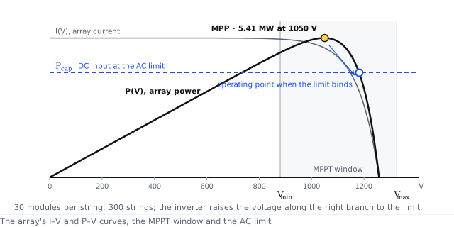
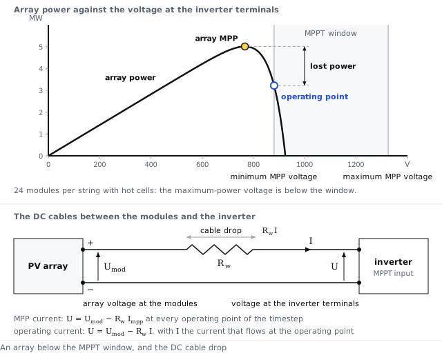
The inverter normally holds the array at its maximum-power point. It also has limits: a highest AC output, which falls as the ambient temperature rises; a window of voltages, from the minimum to the maximum MPP voltage, inside which it can track the maximum-power point; a highest DC input current; and a minimum input power to start. When the array's maximum-power point breaks a limit, the inverter operates the array at another point that respects the limit, and the power between the two points is lost. Each limit has its own row in the loss diagram. The figures show the AC limit and the bottom of the window. The options give nearly the same energy while the array stays inside the window. On strings that run below the window they differ widely, because capping the power without the I–V curve counts no loss for the window.
Options
- Operating point on the array's I–V curve: the operating point moved along the array's I–V curve until every inverter limit holds
- Cap the power, no I–V curve: the DC power capped at the DC current limit and at the AC limit, without a current-voltage curve
- Clip at the AC nameplate: the array at its maximum-power point, with the AC output cut at the nameplate or at the ceiling of a grid power limitation
- MPPT window on the module curve, AC clip: the string held inside the MPPT window on the module curve, the DC derates applied to the power after it, the output cut at the nameplate
References
- PVsyst 8 help, Inverter model and operating limits
API
inverter.operating_point = iv_curve | power_limits | ac_clip | mppt_window