Model option
Hold the MPPT minimum, curve table (PVsyst application)
The array operates at the MPPT minimum, its current interpolated between points of its curve at equal current steps and read 0.24 V and 6 % of the cable drop lower
Inputs used: MPPT window minimum, Modules per string
Method
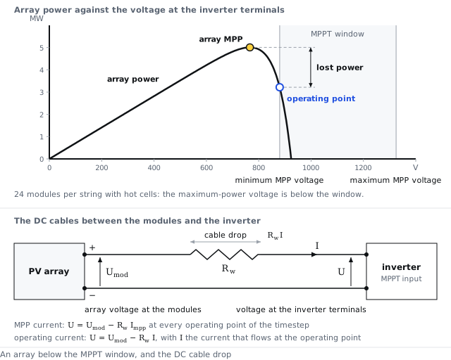
The inverter holds the voltage at its terminals at the MPPT minimum, the inverter's minimum MPP voltage. The array's current there comes from a table of its current-voltage curve. The table holds the maximum-power point and the points whose current lies whole steps of one 29th of the maximum-power current below it, down to the open-circuit voltage (1). The voltage of each point is the voltage at the modules less the cable drop at the maximum-power current. Between two points the current is linear in the voltage (2). The table is read at the floor voltage lowered by a shift (3). The shift is a fitted 0.24 V plus a fitted 6 % of the cable drop at the current read. Over the last 15 % of the way to the maximum-power current it falls linearly to zero (4). The array power at the floor is the floor voltage times that current (5). A floor loss under 0.2 % of the maximum power is not counted. The array power then stays at the maximum power. Otherwise the rest of the maximum power is lost (6).
When the open-circuit voltage less the cable drop is below the floor and the array would not have clipped, the inverter stops. The whole maximum power is then counted in the voltage-threshold row. When the open-circuit voltage less the cable drop is below the floor and the array would have clipped, the table's last segment continues past the open-circuit voltage and is read at the floor itself (7). The current and the power there are negative. The power-limit row then carries the maximum power less that negative power. When the floor point delivers less than the inverter's power threshold, the output is zero. When the floor point exceeds the AC limit, the AC-limit rule of the operating point on the I–V curve raises the voltage from the floor.
Settings
| Setting | Value |
|---|---|
| Current steps from the maximum-power point to open circuit | 29 |
| Fitted voltage offset | 0.24 V |
| Fitted share of the cable drop | 6 % |
| Fitted width over which the shift falls to zero | 15 % of the maximum-power current |
| Smallest counted floor loss | 0.2 % of the maximum power |
The math
- Points of the table
- Table current
- Current at the floor
- Shift
- Power at the floor
- Lost power
- Current past the open-circuit voltage
where
| Symbol | Meaning | Unit |
|---|---|---|
| the current of point | A | |
| the voltage of point at the inverter terminals | V | |
| the number of current steps from the maximum-power point to open circuit | — | |
| the array's maximum-power current of the timestep | A | |
| the voltage at the modules at which the array's curve gives current | V | |
| the DC wiring resistance of one inverter's array | Ω | |
| the table current at voltage at the inverter terminals | A | |
| the array current. At the MPPT minimum | A | |
| the bottom of the inverter's MPPT window | V | |
| the voltage by which the table is read lower at current | V | |
| the fitted voltage offset | V | |
| the fitted share of the cable drop | — | |
| the fitted width over which the shift falls to zero, as a fraction of the maximum-power current | — | |
| the array power at the floor | W | |
| the array power. At its maximum-power point, after the DC losses | W | |
| the smallest floor loss counted, as a fraction of the maximum power | — | |
| the power lost. At the MPPT minimum | W | |
| the open-circuit voltage at the inverter terminals, the voltage at the modules at zero current less | V | |
| the voltage of the table's last point before open circuit, at current | V |
Note
The 0.24 V offset, the 6 % share and the 15 % width are fitted constants with no known physical mechanism. The offset applies to the array voltage, whatever the number of modules per string.
References
- PVsyst 8 help, Inverter model and operating limits
- Analysis of PVsyst 8.1.5 outputs shows this convention in its results.
API
inverter.mppt_floor_behavior = pvsyst_8
Symbols follow the symbol registry.