Model option
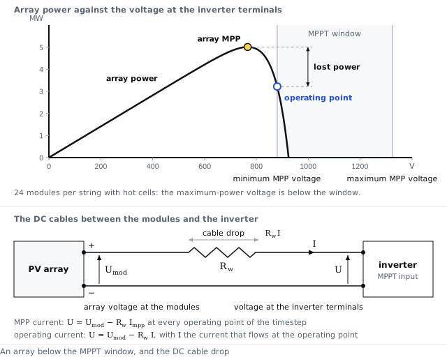
Drop at the MPP current
The cable drop at the maximum-power current, fixed for the timestep
Inputs used: Loss fraction at STC (DC circuit), Global wiring resistance
Method
The voltage lost in the DC cables is computed once per timestep, at the array's maximum-power current, and kept for every operating point of that timestep. At a voltage at the inverter terminals, the array delivers the current its curve gives at . When the inverter stops and no current flows, the reported terminal voltage is the open-circuit voltage less the same drop.
The math
- Voltage at the modules
- Current at the operating point
where
| Symbol | Meaning | Unit |
|---|---|---|
| the voltage at the modules | V | |
| the voltage at the inverter terminals | V | |
| the resistance of the DC cables between the modules and the inverter | Ω | |
| the array's maximum-power current of the timestep | A | |
| the array current at the operating point | A | |
| the current the array delivers at voltage at the modules, from its current-voltage curve | A |
References
- Analysis of PVsyst 8.1.5 outputs shows this convention in its results.
API
inverter.dc_drop_reference = mpp_current
Symbols follow the symbol registry.