Model option
Drop at the operating current
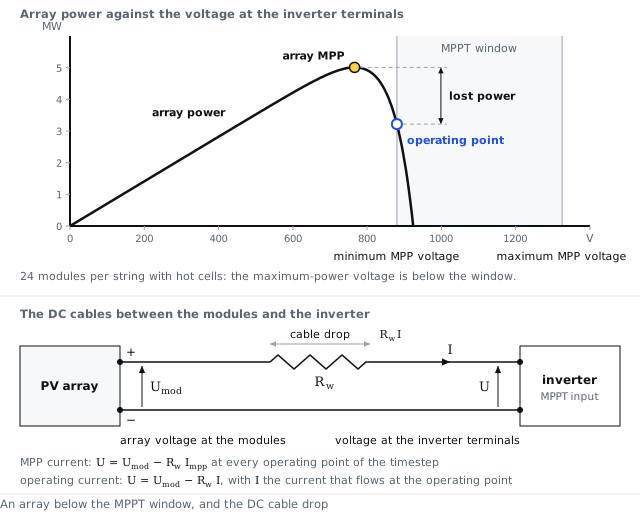
The cable drop at the current of the operating point
Inputs used: Loss fraction at STC (DC circuit), Global wiring resistance
Method
The voltage lost in the DC cables is the cable resistance times the current that flows at the operating point. That current depends on the voltage at the modules, which is the terminal voltage plus the drop, so the current and the drop are solved together at every voltage of the operating-point search. With no current there is no drop, and a stopped inverter sees the array's open-circuit voltage. Solving this way is the same as adding the cable resistance to the series resistance of the array.
The math
- Voltage at the modules
- Current at the operating point, solved together with equation 1
where
| Symbol | Meaning | Unit |
|---|---|---|
| the voltage at the modules | V | |
| the voltage at the inverter terminals | V | |
| the resistance of the DC cables between the modules and the inverter | Ω | |
| the array current at the operating point | A | |
| the current the array delivers at voltage at the modules, from its current-voltage curve | A |
References
- PVsyst 8 help, Array ohmic wiring loss
API
inverter.dc_drop_reference = operating_current
Symbols follow the symbol registry.