Model step
System-level AC losses
Losses on the sum of the inverters
Inputs used: Number of inverters, AC power reference, AC resistive reference, Power factor
What it is
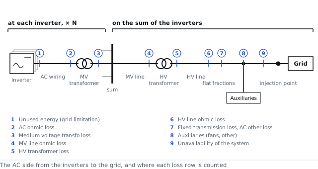
After each inverter's AC wiring and MV transformer, the outputs of all inverters meet on a common busbar. From there the power passes the medium-voltage line, an optional high-voltage transformer and line, and reaches the grid at the injection point. The losses on this path act once, on the sum of the inverters. The sub-steps below the option take them one at a time: the MV line, the HV transformer, the HV line, the flat transmission and other losses, the auxiliary consumption, the grid power limitation and the unavailability. Each can be modelled or switched off, so the same inputs can be run with and without the MV and HV parts. The figure shows the path and the point where each loss row is counted.
Options
- On the sum of the inverters: the system-level losses act once on the sum of the inverter outputs, in the order the power flows
References
- PVsyst 8 help, AC losses
API
ac_losses.use_mv_line, ac_losses.use_hv_transformer, ac_losses.use_hv_line, ac_losses.use_transmission, ac_losses.use_auxiliaries, ac_losses.use_grid_limit, ac_losses.use_unavailability