Reference / System-level AC losses
Model option
On the sum of the inverters
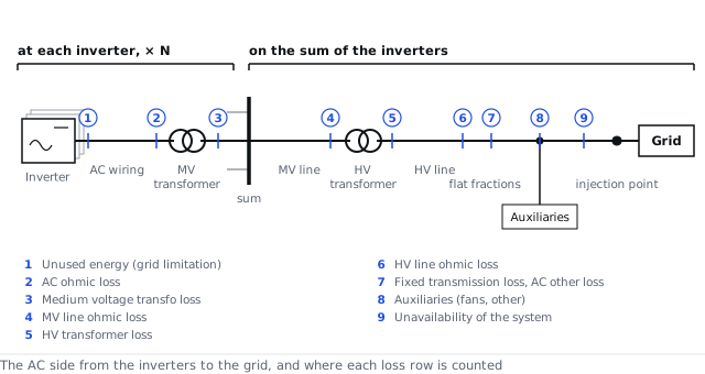
The system-level losses act once on the sum of the inverter outputs, in the order the power flows
Inputs used: Number of inverters, AC power reference, AC resistive reference, Power factor
Method
All inverters are identical, so the power on the busbar is the number of inverters times the output of one, less their AC wiring and MV transformer losses. Equations 3 to 8 take the losses on the sum in the order the power flows. Each resistive part uses the coefficient of equation 1 with its own fraction, on the power the AC resistive reference step sets. The iron loss of the HV transformer is drawn while it is connected. The transmission and other fractions act only on timesteps with export, and the unavailability fraction only on positive power. A shutdown period sets the chain to zero except the night auxiliary draw (Unavailability sub-step). The grid power limitation acts before this chain, on the inverter ceiling. A part switched off in its sub-step is taken as zero. The option has no request key of its own; the sub-steps are switched by the keys listed under API.
The math
- Loss coefficient of a resistive part
- Sum of the inverters
- MV line
- HV transformer
- HV line
- Transmission and other losses
- Auxiliaries
- Unavailability
where
| Symbol | Meaning | Unit |
|---|---|---|
| the loss coefficient of resistive part | 1/W | |
| the loss of part at the reference power and unit power factor, as a fraction of the reference power: is for the MV line, for the copper of the HV transformer and for the HV line | — | |
| the AC power reference of the system: the sum of the inverters' AC nameplates, or the STC reference power (AC power reference step) | W | |
| the power factor | — | |
| the power on the busbar | W | |
| the number of inverters | — | |
| the output of one inverter | W | |
| the AC wiring loss of all inverters | W | |
| the MV transformer loss of all inverters | W | |
| the power after the MV line | W | |
| the power a resistive loss is computed on: the sum of the inverter outputs, or under the cascade reference the power entering the part | W | |
| the power after the HV transformer | W | |
| the iron loss of the HV transformer as a fraction of the reference power | — | |
| the power after the HV line | W | |
| the power after the transmission and other losses | W | |
| the fixed transmission loss fraction | — | |
| the other AC loss fraction | — | |
| the power after the auxiliaries | W | |
| the auxiliary draw of the timestep | W | |
| the power injected into the grid | W | |
| the flat unavailability fraction | — |
References
- PVsyst 8 help, AC losses
API
ac_losses.use_mv_line, ac_losses.use_hv_transformer, ac_losses.use_hv_line, ac_losses.use_transmission, ac_losses.use_auxiliaries, ac_losses.use_grid_limit, ac_losses.use_unavailability
Symbols follow the symbol registry.